
Donald Brown, Ph.D., Consulting Researcher I
Daniel Spring, Ph.D., Group Head, Consulting Researcher II & Consulting Engineer II
Kraig Shipley, P.E., Piping & Fired Heaters; Principal Engineer II
Edrissa Gassama, Ph.D., Consulting Researcher I
In this article, we examine the critical impact of friction and vertical support activity on pipe stress analysis and rotating equipment compliance with a particular emphasis on nozzles in pump piping. Through comprehensive analysis of pipe stress simulation modeling, this study demonstrates that friction and support restraint behavior can significantly affect both piping code compliance and pump nozzle load calculations. We present practical examples showing how these subtle modeling considerations can change system acceptability and provide mitigation strategies for complex multi-operating condition scenarios.
We show that friction effects can cause pump systems that previously met API 610 criteria to become non-compliant. Additionally, vertical support activity varies with thermal conditions and has a direct impact on compliance with design codes. The use of advanced automated tools such as SIMFLEX-IV is shown to offer more reliable handling of complex nonlinear behavior. Finally, systematic approaches to mitigation across a range of operating conditions are essential to ensure consistent performance and regulatory compliance.
Introduction
In the complex world of pipe stress analysis, engineers must balance theoretical understanding with practical implementation challenges. Pipe stress simulators employ one-dimensional beam models to analyze three-dimensional piping networks, calculating stresses for various load cases including weight, thermal, and combined loading conditions. While these tools primarily model elastic behavior, the inclusion of nonlinear support effects introduces significant complexity that can dramatically impact both stress code compliance and rotating equipment load calculations.
The relationship between theoretical models and real-world behavior creates a bridge between academic understanding and practical engineering applications. This relationship becomes particularly important when considering subtle aspects of pipe stress simulation that can completely change the acceptability of a piping system. As noted in Pipe Stress Engineering by L.C. Peng et al., “Sometimes the friction at one support can completely change the acceptability of the piping system.” We show through both academic and real-world case studies that this is indeed the case—friction can have great impacts on nozzle load calculations. We finish by giving pipe-stress modelers a set of best practices when doing their own pipe stress simulations.
Theoretical Foundation
Pipe Stress Simulation Fundamentals
Pipe stress simulators are inherently one-dimensional beam models that represent three-dimensional piping networks. These tools, including SIMFLEX-IV, CAESAR II, and AutoPIPE, calculate stresses for various load cases while primarily modeling elastic behavior. The simulation process is driven by codes and standards, particularly ASME B31.3, which can result in modeling choices that may seem unusual from a purely numerical perspective.
Learn More About Equity Software’s Cloud-Based Piping Stress Analysis Software
A critical aspect of pipe stress modeling is its inherent subjectivity—as there are multiple ways to model the same physical situation, engineering judgment is required. This subjectivity becomes particularly important when dealing with nonlinear support behavior and friction effects. The main purpose of pipe stress simulators is to give analysts a bridge between the modeled piping system and its code compliance in the real-world industrial plant (see Figure 1).

Of the multitude of considerations and choices when modeling a piping network, two modeling techniques stand out most as having the highest impact but are often overlooked. These are 1) vertical support activity and 2) friction modeling. Vertical supports can uplift during different thermal conditions, and their activity can greatly affect the results. Friction at supports is one of the most nonlinear behaviors in modern pipe stress software and is often overlooked as it is just a checked option box.
Vertical Support Activity
Vertical single-acting restraints represent one of the most significant sources of nonlinearity in pipe stress analysis. These supports can uplift under various thermal conditions, creating different support configurations across operating states. The mathematical nonlinearity introduced by this behavior affects:
- Code Compliance: Different support activities lead to varying sustained stress distributions
- Load Distribution: Changes in support activity alter force paths through the piping system
- Operating Conditions: Support activity varies between cold, hot, and transitional states
A classic example of this can be found in the B31.3 Appendix S, S302.1, where during the cold condition a support is active, but during the operating condition the support inactivates, causing issues when evaluating sustained stress code compliance. The complexity of manually determining support activities across multiple operating conditions makes automated determination essential. SIMFLEX-IV automatically determines support activity through auxiliary solve procedures before compliance load cases, eliminating the traditional bottleneck of manual support activity determination (see Figure 2).

Friction Modeling
Support friction introduces a high degree of nonlinearity into pipe stress calculations, fundamentally altering the way loads are distributed and absorbed throughout a piping system. This nonlinear behavior presents several challenges for both analysis accuracy and computational stability. Friction primarily feeds into system stability, load transfer, and, most importantly for this article, equipment loads.
One of the primary concerns is system stability. While friction can provide beneficial energy dissipation and reduce movement under certain conditions, it also introduces discontinuities in the load-deformation response. These discontinuities can make it difficult for solvers to achieve convergence, particularly in large or complex models with numerous supports and load combinations.
Friction also significantly affects load transfer within the system. Unlike a frictionless model where supports allow free sliding or idealized constraints, the presence of friction restricts movement in a more complex, directionally dependent manner. This restriction alters how thermal expansion forces, sustained loads, and dynamic effects are distributed across the piping network. As a result, support reactions become more unpredictable, and certain components may experience localized overloads that would not be apparent in a simplified model.
Perhaps most critically, equipment loads—especially on sensitive components such as pumps, turbines, and air coolers—are directly influenced by the presence of support friction. Friction can cause a significant increase in the forces and moments transmitted to equipment nozzles, potentially pushing loads beyond allowable limits and leading to non-compliance with industry standards such as API 610 or NEMA SM-23.
To address these challenges, SIMFLEX-IV employs an implicit stiffness-based friction model, which offers substantial advantages over traditional explicit force-based methods used in many other pipe stress simulators (see Figure 3). The implicit approach integrates friction behavior directly into the system stiffness matrix, resulting in a smoother and more stable solution process. This method greatly reduces convergence problems commonly associated with force-controlled friction models while preserving the physical realism required for accurate engineering decisions. By combining robust numerical methods with realistic friction modeling, SIMFLEX-IV enhances both the reliability and efficiency of piping system analyses.

Methodology and Analysis Verification
Validation of Friction Modeling Approaches
To ensure the accuracy and reliability of friction modeling within SIMFLEX-IV, a series of comprehensive unit tests were conducted. These tests compared the simulation results from SIMFLEX-IV against two well-established tools: CAESAR II, a widely used commercial pipe stress analysis program, and Abaqus, a high-fidelity finite element analysis (FEA) platform known for its advanced nonlinear capabilities. The objective was to validate both the mathematical formulation and the numerical stability of SIMFLEX-IV’s friction modeling under controlled, well-understood conditions.
Two representative test cases were selected to capture the essential behaviors associated with support friction, including both basic loading scenarios and more complex directionally dependent friction effects.
Unit Test 1: Simple Two-Element System
The first test case involved a basic cantilever beam model composed of two pipe elements with a single support. A friction coefficient of 0.4 was applied at the support to introduce realistic resistance to sliding. Weight and thermal loads were applied across the beam to induce a combination of axial, bending, and shear forces. The goal was to evaluate how each software package computed nodal forces and moments under the influence of friction, and to ensure consistency in the interpretation of support behavior.

This simplified scenario served as a baseline for direct comparison, where discrepancies could be easily attributed to differences in numerical formulation rather than geometric complexity.
Unit Test 2: Angled Cantilever Beam
The second unit test introduced a more geometrically complex cantilever beam angled in space, designed to rigorously test the handling of directional friction effects. This setup imposed multi-directional loading conditions and varied contact orientations, providing a deeper assessment of each solver’s ability to resolve friction forces in multiple axes. The model included constraints and load combinations that would typically challenge convergence and reveal any limitations in the friction formulation.

This test was particularly useful for evaluating not just the magnitude of calculated forces but also the convergence behavior and numerical accuracy under conditions of high nonlinearity.
Results and Observations
The comparison indicated SIMFLEX-IV’s output showed excellent agreement with Abaqus, particularly in the calculation of support reaction forces and moments influenced by friction. This consistency confirms that the implicit stiffness-based friction model in SIMFLEX-IV performs comparably to the more computationally intensive nonlinear FEA methods.
CAESAR II also produced generally similar results; however, it exhibited small but consistent differences in friction force predictions, typically ranging from 2.5% to 5% when compared to Abaqus and SIMFLEX-IV. These deviations may be attributed to differences in friction modeling methodology, such as CAESAR II’s use of explicit force-based formulations and varying convergence criteria.
Overall, the unit testing provided strong validation of SIMFLEX-IV’s friction modeling capability, demonstrating both numerical stability and high physical fidelity in a range of conditions. This reinforces confidence in the tool’s applicability to real-world piping systems where accurate friction behavior is critical to assessing system compliance and equipment protection.
Pump Piping Code Compliance Framework: API 610
API 610 is a widely recognized standard for centrifugal pumps used in the oil, gas, and petrochemical industries. It sets strict requirements for pump design, materials, and testing to ensure high reliability and durability. A key feature of the standard is its limits on allowable nozzle loads, which help prevent misalignment, vibration, and premature pump seal failure. Compliance with API 610 is essential for maintaining safe and reliable pump operation in demanding industrial environments. The logic branching of the code relies on the type of pump and orientation, e.g., vertical vs. horizontal (see Figure 6). For simplicity, this discussion focuses on focus on horizontal pumps.

Pump code compliance is evaluated using the combined thermal and weight load case representing typical operating conditions. For stress code compliance, the analysis is performed separately using a thermal (expansion) load case and a weight (sustained) load case, which are then combined during the stress calculations to assess overall code compliance. This approach ensures accurate representation of both operating and sustained load effects on the piping system. The analysis methodology incorporates three API 610 Annex F criteria for horizontal pump piping.
Criteria 1: Table-based approach using API 610 Table 5 values multiplied by factor of 2.0 for enhanced allowables (see Figure 7). Allowable forces and moments listed in Table 5 may be increased by a factor of 2.0 provided that a more detailed analysis (e.g., F.4 in API 610) demonstrates that the resulting stresses in the pump components remain within acceptable limits. However, one must perform a stress check (for example, with a pipe stress simulator) to validate that the higher loads are acceptable. This criterion is simply a table lookup and requires the analyst to confirm the computed moments and forces are below the thresholds.

Criteria 2: Force-moment ratio combined force and moment evaluation using the relationship. This criterion is more complicated and requires a ratio of forces and moments and is more complex than the simple table lookup (see Figure 8).

Criteria 3: Discharge/suction coupling evaluation of combined effects resolved to pump centerline, accounting for interaction between suction and discharge nozzles. This is the most complex criteria and involved a coupling of the system at suction and discharge (see Figure 9).

Case Studies and Results
This section highlights how friction can significantly impact the code compliance of rotating equipment, particularly with respect to API 610 nozzle load limits.
Single Pump Analysis
A detailed analysis was conducted on a single pump system to illustrate the influence of friction on API 610 compliance. The system consisted of an NPS 8 suction line (carbon steel, Schedule 40) and an NPS 6 discharge line (carbon steel, Schedule 80), operating at 450°F (232°C) on the suction side and 500°F (260°C) on the discharge. Multiple support configurations were included, such as guides and spring hangers, to reflect a realistic piping layout (see Figure 10).

In the analysis without friction, both pump nozzles passed all API 610 criteria with comfortable margins. The suction nozzle (Node 80) showed forces and moments well below allowable limits, while the discharge nozzle (Node 95) demonstrated excellent compliance.
However, when friction was introduced (coefficient μ = 0.4), the situation changed significantly. The NPS 6 suction nozzle failed API 610 criteria due to increased load levels. Specifically, the force reaction (FRA) increased from 479 lbf (0.217 tf) to 1247 lbf (0.565 tf) (allowable of 1010 lbf [0.458 tf]), and the moment reaction (MRA) rose from 2938 ft-lbf (0.406 m-tf) to 3758 ft-lbf (0.519 m-tf) (allowable of 2310 ft-lbf (0.319 m-tf)).

This example clearly demonstrates that friction can transform a system from compliant to non-compliant, emphasizing the need for effective mitigation strategies.
Mitigation Strategies
Two mitigation approaches proved effective in restoring compliance:
- Spring Hanger Addition: Installing properly sized spring hangers while removing rigid supports allowed for controlled movement, reducing nozzle loads to acceptable levels.
- Restraint Relocation: Moving specific restraints away from areas with high stress concentrations helped redistribute loads more evenly across the system.


The second strategy of moving the restraint demonstrates how sensitive supports can be to the addition of friction and hammers home Peng’s statement that “Sometimes the friction at one support can completely change the acceptability of the piping system.”
Multi-Pump System Analysis
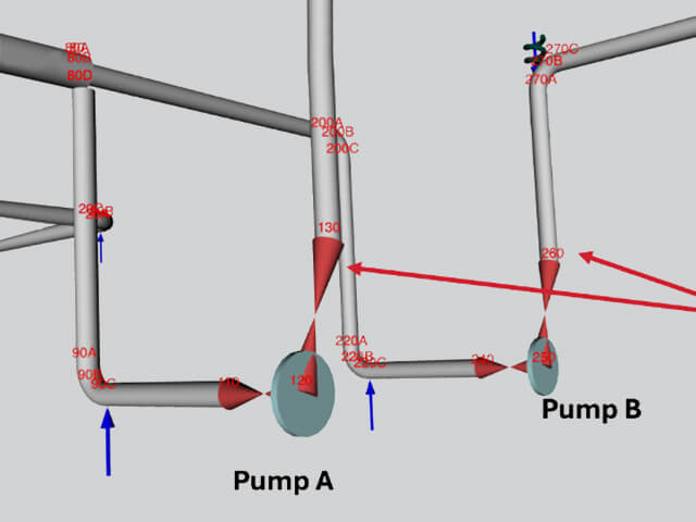
The single pump model effectively bifurcates the system into two pieces, thus making the third coupling criterion of API 610 a moot point. The system is spliced into two non-interacting pieces at suction and discharge. This is hardly the case in industrial applications. To showcase this, a more complex dual pump system was analyzed to evaluate friction effects across multiple operating conditions. We can enumerate the temperature conditions as follows:
- Condition 1: Pump A operational, Pump B idle
- Condition 2: Both pumps operational
- Condition 3: Pump A idle, Pump B operational
This case study ensures the pipe stress model must consider all three criteria of API 610 Annex F. The case study presents many problems in ensuring rotating equipment compliance. The main challenge was developing mitigation strategies that worked consistently across all three operating scenarios rather than solving for one condition at the expense of another (see Figure 13).

Mitigation Strategies
The piping system again was modeled using SIMFLEX-IV (see Figure 14). Unsurprisingly, the mitigation strategies required for the dual pump system to satisfy compliance across temperature regimes were a challenge. A guess-and-check strategy proved to not be fruitful in searching for a proper mitigation technique to ensure compliance; a more strategic approach was required, and friction complicated things along the way.

By applying a systematic analysis, it was revealed that the moments in the Z-direction were persistently problematic in every thermal condition. This led to a strategy of trying to lower this moment, as it appeared to be pushing our model into failure via Criteria 2 and 3 of API 610. The solution involved strategic restraint placement to control system movement, particularly in the X-Y plane. While Y-direction supports were already adequate, two X-direction restraints were added at critical points in the layout to improve stability and reduce excessive moment loads (see Figure 15). The addition of these restraints lowered the offending Z-directional moments.

As a result, this approach successfully addressed compliance concerns across all operating conditions. The case illustrates the importance of comprehensive, system-level analysis when dealing with multiple operating scenarios rather than relying on condition-specific fixes that may not generalize. As always, do not forget to add support friction to the mix as this can greatly change the forces and moments at the nozzle junctions. Fortunately, the mitigation strategy of adding X-directional support satisfied the compliance conditions across thermal conditions as well as with (or without) the inclusion of friction.
Implications for Pipe Stress Modelers
Impact on Code Compliance
The research clearly demonstrates that friction effects can fundamentally alter the outcomes of pipe stress analysis. When friction is included in the model, forces and moments can increase by 50% or more, significantly impacting the accuracy of stress predictions. Systems that appear compliant under frictionless assumptions may in fact fail when realistic friction conditions are considered. Furthermore, friction greatly influences which supports become active during operation, altering the load paths and potentially compromising code compliance.
Equipment Load Sensitivity
Rotating equipment, especially pumps, exhibits a high degree of sensitivity to the presence of friction. In many cases, the margin for compliance with API 610 requirements can be eliminated once friction is considered. Friction alters the way loads are distributed across the system, often in ways that are not intuitive under simplified assumptions. This complexity is further compounded when multiple operating conditions must be considered, increasing the challenge of maintaining acceptable equipment loads.
Mitigation Strategy Requirements
To effectively manage the impact of friction and maintain code compliance, a systematic mitigation strategy is essential. Solutions must be robust across all anticipated operating conditions, not just a single case. This requires detailed root cause analysis to understand why specific loads exceed acceptable thresholds. A range of mitigation techniques should be considered—including the use of spring hangers, relocation of restraints, addition of directional restraints, and enhancements to system flexibility—all tailored to the specific challenges of the system in question.
Mistakes and Best Practice for Pipe System Modeling
Piping stress analysis plays a critical role in ensuring the safety, reliability, and longevity of process systems. However, even experienced analysts can overlook key modeling considerations, leading to inaccurate results or non-compliance with design codes. Through extensive third-party reviews and industry experience, several common modeling mistakes and best practices have been identified. Addressing these issues early in the design process can significantly improve system performance and reduce the risk of costly rework or equipment failure. The following outlines the most frequent pitfalls observed in piping stress models, along with practical recommendations to enhance analysis accuracy and engineering integrity.
Common Modeling Mistakes
- Ignoring elbow stiffening due to trunnions or flanged ends, leading to underestimated stress concentrations
- Omitting friction effects or using incorrect friction coefficients, causing unrealistic load distribution
- Incorrect thermal growth values across equipment operating conditions, especially for rotating machinery
- Incomplete or inaccurate definition of operating conditions, reducing the reliability of the analysis
- Wrong component weights, particularly for heavy items (valves, flanges, accessories), affecting support/load calculations
- Incorrect flange classification, such as wrong pressure class, leading to non-compliance with design codes
- Use of incorrect material properties, resulting in invalid allowable stress calculations
- Improper wind loading definitions, including errors in model elevation or wind pressure parameters
- Neglecting thermal growth of vessel-mounted supports, impacting load paths and support behavior
- Mischaracterizing internal contents, including:
- Specific gravity
- Insulation
- Jacketing
- These can significantly affect system response and weight distribution.
Best Practice Recommendations
- Model nozzle flexibility to reduce thermal stress and improve load distribution accuracy.
- Use rigid elements or equivalent pipe sections to simulate equipment thermal behavior more accurately.
- Reduce flexibility in elbows with attached trunnions or flanges, as they stiffen the geometry.
- Always include friction in equipment load assessments.
- Design spring hangers to release vertical load at sensitive anchor points, minimizing unintended load transfer.
- Control spring variability, with suggested limits:
- ≤ 6% for cyclic conditions
- ≤ 10% for rotating equipment
- ≤ 15% for systems above 500°F (260°C)
- Use appropriate tools for equipment assessment, such as:
- WRC 537
- PD5500
- Finite element analysis (FEA)
- Analyze flange loading for leakage risks using correct design standards.
- Model expansion joints completely, including all hardware, to capture realistic behavior.
- Incorporate sway struts and realistic anchor stiffness into dynamic analysis for accurate vibration response.
Advanced Computational Considerations
Numerical Stability
Implementing friction modeling in piping stress analysis requires careful consideration of numerical methods to ensure reliable and accurate results. One key distinction lies in the choice between implicit and explicit solution techniques. Implicit, stiffness-based methods are generally preferred, as they offer superior numerical stability, particularly in complex systems where nonlinear behavior is present. Additionally, setting appropriate convergence criteria is critical—overly loose tolerances can lead to false convergence, while overly strict settings may cause unnecessary solution delays. Load stepping must also be carefully managed—selecting proper increment sizes helps maintain both accuracy and computational efficiency throughout the analysis process.
Automation Benefits
The use of advanced analysis tools, such as SIMFLEX-IV, brings substantial benefits to the modeling and evaluation process. One of the most significant advantages is the automation of support activity determination, which eliminates the need for manual identification of active and inactive supports under varying load conditions. These tools also enable more stable friction modeling by avoiding the convergence issues often associated with force-based approaches. Moreover, comprehensive post-processing capabilities allow for automated compliance checking across multiple design criteria, significantly reducing the potential for oversight and improving overall analysis quality.
Conclusions and Recommendations
This comprehensive analysis demonstrates the critical importance of including friction and support activity effects in pipe stress analysis. The research shows that these subtle modeling considerations can completely change system acceptability, transforming compliant designs into non-compliant ones.
Key Recommendations
- Always Include Friction: Friction effects should be considered in all piping assessments, with comparative analysis (with and without friction) to bound the effects
- Automate Support Activity: Use tools that automatically determine support activity across thermal conditions rather than manual specification
- Systematic Mitigation: Develop mitigation strategies that address all operating conditions simultaneously rather than individual case solutions
- Best Practice Implementation: Follow established modeling guidelines to avoid common mistakes that can invalidate analysis results
Future Considerations
As automated FEA solutions become more accessible and computational power continues to increase, the historical trade-offs between accuracy and computational cost are diminishing. This trend suggests that more sophisticated modeling approaches, including detailed friction and nonlinear support behavior, will become standard practice rather than specialized applications.
The bridge between theoretical understanding and practical implementation will continue to evolve, with tools like SIMFLEX-IV leading the development of more reliable, automated, and comprehensive pipe stress analysis capabilities.
Final Thoughts
The complexity of pipe stress analysis requires careful consideration of multiple interacting effects. Friction and support activity represent just two of many subtle factors that can significantly impact results. As the industry continues to demand higher accuracy and reliability, the integration of advanced computational methods with practical engineering judgment becomes increasingly important.
Success in pipe stress analysis requires not only understanding the theoretical foundations but also appreciating the practical implications of modeling choices. The examples presented in this article demonstrate that seemingly minor modeling decisions can have major impacts on system acceptability, equipment loads, and, ultimately, operational safety and reliability.
Please send any questions to the authors by submitting the form below:
This article is based on research conducted by The Equity Engineering Group, Inc., presented at the 2025 Equity Symposium. For additional information or technical support, contact the authors at sales@e2g.com or visit www.e2g.com.